Introduction to tho three types based on their coil control methods: single-coil control, dual-coil control, and energy-saving board control (i.e., PWM control board + single-coil control). This article compares the structure, working principle, and energy consumption characteristics of DC contactors with single-coil, dual-coil, and PWM control methods, and analyzes their advantages, disadvantages, and applicability.
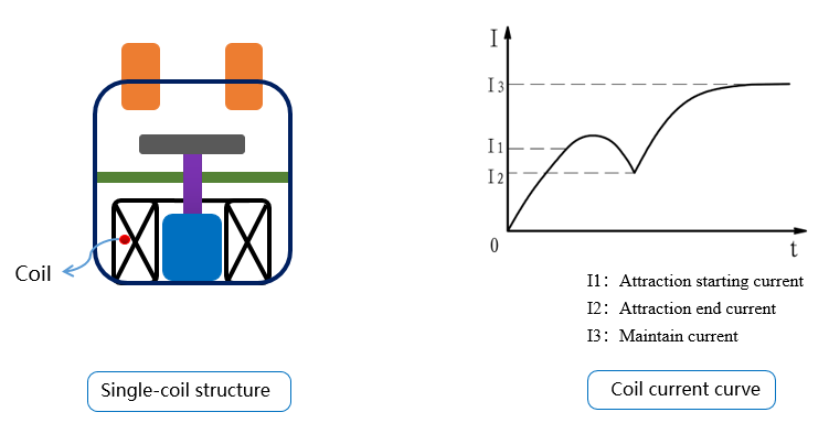
The main components of a single-coil DC contactor include a single coil, a spring reset mechanism, and a contact system. Its working principle is that when the coil is continuously energized, a magnetic field is generated, which causes the armature to move upward, bringing the moving contact close to stationary contact, the normally open contact is connected. When the coil is de-energized, the electromagnetic suction force disappears, causing the moving contact to return to its original position, so that the normally open contact is disconnected.
As a core component of power control systems, the performance and energy consumption of DC contactors directly affect system efficiency. Generally, DC contactors can be classified intact with the stationary contact. When the power is cut off, the spring resets, and the moving and stationary contacts separate. The main disadvantages of single-coil DC contactors are as follows:
① Generally, the energy consumption is relatively high, i.e., P = I⊃2; * R (with full current operation I = Us / R), so the coil temperature rise of a single-coil DC contactor is usually the highest.
② When the coil control circuit of a single-coil DC contactor is de-energized, a large reverse electromotive force is generated. For DC contactors with a control voltage of 12V DC or 24V DC, hundreds of volts of reverse voltage will be generated at the moment of coil de-energization. The common solution is to parallel a freewheeling diode in the coil control circuit (this method usually leads to a longer release time of the main contacts when the DC contactor is de-energized, so a TVS diode or a freewheeling diode in series with a zener diode is often used in parallel with the coil control circuit).
③ The operating voltage range of the coil (Us) is small, generally 85% Ue to 110% Ue (Ue represents the rated operating voltage of the product).
The main advantages of single-coil DC contactors are low manufacturing cost and strong resistance to electromagnetic interference (EMC).
![]()
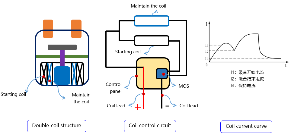
The main structure of a double-coil DC contactor consists of a starting coil (high current), a holding coil (low current), a circuit switching control board, a spring reset mechanism, and a contact system. Its working principle is that when the coil is initially powered on, the starting coil and the holding coil are connected in parallel and energized simultaneously, generating a strong electromagnetic field to provide a sufficient initial electromagnetic force, which lasts for approximately 130 ms. Then, the circuit switching control board cuts off the starting coil, leaving only the holding coil to continuously operate, providing an appropriate magnetic field to maintain the normal closed state of the product. The main disadvantages of a double-coil DC contactor are as follows:
① The starting power is relatively high, denoted as P_start, thus requiring a power supply with a high capacity.
② The manufacturing cost of a double-coil DC contactor is relatively high, mainly due to the complexity of the coil assembly process and the addition of the circuit switching control board.
③ The operating voltage range of the coils (U_s) is small, typically ranging from 85% U_e to 110% U_e (U_e represents the rated operating voltage of the product).
The main advantage of a double-coil DC contactor is that the power consumption during continuous operation of the coils is low, denoted as P_hold, and there is no significant reverse voltage generated (which has been suppressed by the circuit switching control board).
![]()
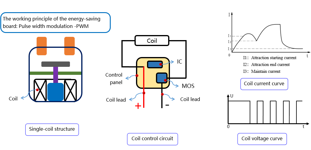
The main structural components of the energy-saving board DC contactor include a single coil, a PWM circuit control board, a spring reset mechanism, and a contact system. Its working principle is that during the start-up phase, the coil is powered by full voltage (the start-up phase lasts approximately 130ms), and during the holding phase, the current is reduced by adjusting the duty cycle of the voltage output (PWM pulse width modulation). The main disadvantages of the energy-saving board DC contactor are as follows:
① The start-up power consumption is generally high, i.e., Pstart (during the start-up phase), so the power supply power required for use is relatively large.
② The manufacturing cost of the energy-saving board DC contactor is relatively high, mainly due to the complex processing of the coil assembly and the addition of the energy-saving control board.
③ The anti-electromagnetic interference (EMC) capability is weak, mainly because there are multiple new ICs on the energy-saving control board and it relies on software program control.
The main advantages of the energy-saving board DC contactor are that the continuous working energy consumption of the product is extremely low, i.e., the coil temperature rise is low, the working voltage range of the coil is wide, and there is no significant reverse voltage generated (which has been suppressed by the energy-saving control board).
![]()
In summary, the differences among the three different coil control methods of DC contactors are summarized in the following table,
| Single-coil | Double-coil | Energy-saving board |
Starting current | low | high | high |
Maintain current | big | low | low |
Maintain electromagnetic force | Unchanged | Get smaller | Unchanged |
Coil operating voltage range | 85%-110% US | 85%-110% US | 宽电压 |
Coil temperature rise | high | low | low |
Coil polarity | Non-polarity | polarity | polarity |
Reverse electromotive force | Yes | No | No |